Add to Cart
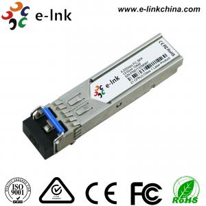
4.25G Single Mode Dual Fiber 10km 1310nm SFP Optical Transceiver Module
Features
Applications
Description
The transceiver consists of three sections: a DFB laser transmitter, a PIN photodiode integrated with a trans-impedance preamplifier (TIA) and MCU control unit. All modules satisfy class I laser safety requirements.
The transceivers are compatible with the Small Form Factor Pluggable Multi-Sourcing Agreement (MSA)1. They are compatible with Fiber Channel per FC-PI-2 Rev. 10.0. also simultaneously compatible with Gigabit Ethernet as specified in IEEE Std 802.3.
Absolute Maximum Ratings
Table 1 - Absolute Maximum Ratings
| Parameter | Symbol | Min | Max | Unit |
| Power Supply Voltage | Vcc-Vee | 0 | 3.6 | V |
| Operating Case Temperature (Commercial) | Tc | 0 | 70 | °C |
| Operating Case Temperature (Industrial) | Tc | -40 | +85 | °C |
| Storage Temperature | Ts | -40 | +85 | °C |
| Operating Humidity | - | 5 | 90 | % |
Recommended Operating Conditions
Table 2 - Recommended Operating Conditions
| Parameter | Symbol | Min | Typical | Max | Unit | |
| Operating Case Temperature |
Standard Industrial |
Tc Tc |
0 -40 |
+70 +85 |
°C °C |
|
| Power Supply Voltage | Vcc | 3.13 | 3.3 | 3.47 | V | |
| Power Supply Current | Icc | 300 | mA | |||
| Data Rate | 4.25 | Gbps | ||||
Optical and Electrical Characteristics
Table 3 - Optical and Electrical Characteristics
| Parameter | Symbol | Min | Typical | Max | Unit | Notes | ||
| Transmitter | ||||||||
| Date Rate | 4.25 | Gb/S | ||||||
| Centre Wavelength | λc | 1260 | 1310 | 1360 | nm | |||
| Spectral Width (-20dB) | ∆λ | 1 | nm | |||||
| Side Mode Suppression Ratio | SMSR | 30 | dB | |||||
| Average Output Power (BOL) | Pout | -8 | 0 | dBm | 1 | |||
| Extinction Ratio | ER | 5 | dB | |||||
|
Average Launch Power-OFF Transmitter |
Pout | -40 | dBm | |||||
| Optical Eye Diagram | Fiber Channel Compliant | |||||||
| Optical Rise/Fall Time(20%~80%) | tr/tf | 130 | ns | |||||
| Data Input Swing Differential | VIN | 200 | 2400 | mV | 2 | |||
| Input Differential Impedance | ZIN | 90 | 100 | 120 | Ω | |||
| TX Disable | Disable | 2.0 | Vcc | V | ||||
| Enable | 0 | 0.8 | V | |||||
| TX Fault | Fault | 2.0 | Vcc | V | ||||
| Normal | 0 | 0.8 | V | |||||
| Receiver | ||||||||
| Centre Wavelength | λc | 1260 | 1360 | nm | ||||
| Receiver Sensitivity (BOL) | Sen | -18 | dBm | 3 | ||||
| LOS De-Assert | LOSD | -18 | dBm | |||||
| LOS Assert | LOSA | -28 | dBm | |||||
| LOS Hysteresis | 0.5 | 6 | dB | |||||
| Receiver Reflectance | -20 | dB | ||||||
| Data Output Swing Differential | Vout | 350 | 1800 | mV | 4 | |||
| Loss of Signal (LOS) Assert Time | TAssert | 500 | nS | |||||
| Loss of Signal (LOS) DeassertTime | TDeassert | 500 | nS | |||||
| LOS | High | 2.0 | Vcc | V | ||||
| Low | 0 | 0.8 | V | |||||
Notes:
1. The optical power is launched into SMF.
2. PECL input, internally AC-coupled and terminated.
3. Measured with a PRBS 27-1 test pattern @4250Mbps, BER ≤1×10-12
4. Internally AC-coupled.
Timing and Electrical
Table 4 - Timing and Electrical
| Parameter | Symbol | Min | Typical | Max | Unit |
| Tx Disable Negate Time | t_on | 1 | ms | ||
| Tx Disable Assert Time | t_off | 10 | µs | ||
| Time To Initialize, including Reset of Tx Fault | t_init | 300 | ms | ||
| Tx Fault Assert Time | t_fault | 100 | µs | ||
| Tx Disable To Reset | t_reset | 10 | µs | ||
| LOS Assert Time | t_loss_on | 100 | µs | ||
| LOS De-assert Time | t_loss_off | 100 | µs | ||
| Serial ID Clock Rate | f_serial_clock | 400 | KHz | ||
| MOD_DEF (0:2)-High | VH | 2 | Vcc | V | |
| MOD_DEF (0:2)-Low | VL | 0.8 | V |
Diagnostics
Table 5 – Diagnostics Specification
| Parameter | Range | Unit | Accuracy | Calibration |
| Temperature | 0 to +70 | °C | ±3°C | Internal / External |
| -40 to +85 | ||||
| Voltage | 3.0 to 3.6 | V | ±3% | Internal / External |
| Bias Current | 0 to 100 | mA | ±10% | Internal / External |
| TX Power | -9 to -3 | dBm | ±3dB | Internal / External |
| RX Power | -23 to -3 | dBm | ±3dB | Internal / External |
Digital Diagnostic Memory Map
The transceivers provide serial ID memory contents and diagnostic information about the present operating conditions by the 2-wire serial interface (SCL, SDA).
The diagnostic information with internal calibration or external calibration all are implemented, including received power monitoring, transmitted power monitoring, bias current monitoring, supply voltage monitoring and temperature monitoring.